How Does a 3 Phase Motor Work? A Comprehensive Guide to Its Core Principles
Of course, here is the comprehensive, long-form article based on your instructions.
Table of Contents
- The Stator: The Stationary Heart
- The Rotor: The Part That Spins
- The Air Gap: The Crucial Empty Space
- Step 1: Generating the Rotating Magnetic Field (RMF)
- Step 2: Electromagnetic Induction in the Rotor
- Step 3: Producing Torque and Rotation
- Step 4: The Concept of “Slip” – The Secret to It All
1. Introduction: Unveiling the Powerhouse of Industry
I remember the first time I really thought about a 3-phase motor. I was an apprentice, standing on a factory floor, surrounded by the hum of machinery. My mentor pointed to a large, finned metal cylinder driving a massive conveyor belt and said, “That’s the heart of this entire operation. Understand that, and you’ll understand how industry moves.”
He was right. A 3-phase motor is, in many ways, the powerhouse of the modern world. It’s an electrical machine that converts three-phase alternating current (AC) electrical energy into mechanical energy. But that definition sounds a bit dry, doesn’t it?
Let’s put it another way: it’s the simple, rugged, and incredibly efficient workhorse that drives everything from industrial pumps and fans to elevators and manufacturing equipment. If you’ve ever wondered how electricity generates such powerful and consistent motion, you’ve come to the right place.
Understanding its operation isn’t just for electrical engineers. Knowing how it works helps you appreciate its efficiency, its reliability, and why it’s used in virtually every heavy-duty application imaginable. The key takeaway, and what I hope you’ll see by the end of this, is the beautiful simplicity behind its powerful design. It’s a marvel of physics and engineering, and I’m excited to break it down for you.
2. Understanding the Foundation: What is 3-Phase Power?
Before we can even peek inside the motor, we have to talk about the fuel that makes it run: 3-phase power. When I first started, this concept felt a bit abstract. I was used to the simple single-phase power in my home—the kind that comes from a standard wall outlet.
Here’s the difference in a nutshell. Single-phase power delivers electricity in a single wave. It rises to a peak, falls to zero, reverses, and repeats. This means the power delivery isn’t constant; it pulses.
Three-phase power, on the other hand, is a much smoother and more powerful beast. It consists of three separate alternating currents delivered on three separate wires. The magic is that each of these currents is perfectly out of sync with the others. They are “phase-shifted” by 120 degrees.
Imagine three people pushing a merry-go-round.
- If only one person (single-phase) pushes, the ride gets a shove, then slows down, then gets another shove. It’s jerky.
- But if three people (three-phase) stand equally spaced around it and each pushes in perfect sequence, the merry-go-round spins smoothly and continuously.
That’s the core advantage of 3-phase power. It delivers constant, non-pulsating power. This makes it incredibly efficient for power transmission over long distances and, most importantly for our topic, gives motors the unique ability to start on their own without any complex extra parts. It’s the perfect fuel for a powerful engine.
3. The Anatomy of a 3-Phase Motor: My First Look Inside
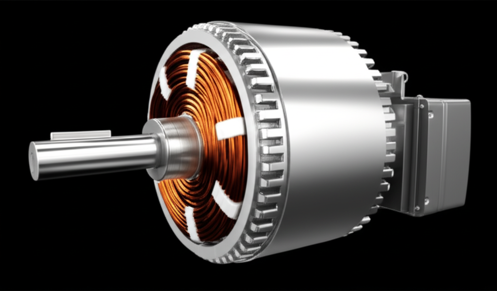
The day I got to take apart an old squirrel cage motor was a real eye-opener. I was expecting a complex mess of wires and gears, but what I found was remarkably simple. There are really only two main parts that do all the work, with a critical space between them.
The Stator: The Stationary Heart
The stator is the big, heavy, stationary outer part of the motor. If you look at a motor from the outside, the finned casing you see is protecting the stator. When we cracked it open, I saw two key things:
- Laminated Core: The frame was filled with a stack of very thin, insulated metal plates. My mentor explained that this wasn’t a solid block of iron for a very specific reason: to reduce energy losses from something called “eddy currents.” By using thin plates, the quality of the stator core lamination directly improves the motor’s efficiency by preventing unwanted currents from swirling around in the core and generating heat.
- Three Sets of Windings: Neatly tucked into slots within this core were coils of copper wire. There were three distinct sets of these windings, one for each phase of the incoming three-phase power.
The stator’s one and only job is to take that 3-phase AC supply and use it to create a rotating magnetic field. It’s the part that sets the stage for all the magic to happen.
The Rotor: The Part That Spins
Sitting inside the stator, but not touching it, was the rotor. This is the inner part that spins and is connected to the shaft that drives the machinery. The most common type, and the one I saw that day, is called a squirrel cage rotor.
It honestly looks a bit like a hamster wheel or, as the name suggests, a cage for a squirrel. Here’s its construction:
- It also has a laminated iron core to keep those pesky eddy current losses down. High-quality rotor core lamination is just as important here as it is in the stator.
- Instead of windings, it has thick bars of aluminum or copper running through the core.
- These bars are all connected at both ends by short-circuiting “end rings.”
That’s it. No wires connecting to it, no brushes, no separate power supply. It’s just a beautifully simple, rugged cylinder of metal bars. Its job is to have a current induced into it by the stator’s magnetic field, which ultimately makes it spin.
There is another type, called a wound rotor, which has actual windings and slip rings, but you’ll find the squirrel cage in over 90% of industrial motors because of its simplicity and durability.
The Air Gap: The Crucial Empty Space
Finally, there’s the tiny, uniform gap between the stator and the rotor. This is the air gap. It might seem like nothing, but it’s one of the most critical design elements of the motor.
This gap is where the magnetic field from the stator projects across to interact with the rotor. It has to be as small as possible to ensure a strong magnetic connection and high efficiency but large enough to prevent the rotor from scraping against the stator. It’s a delicate engineering balance.
4. The Core Principle: How a 3-Phase Motor Works (Step-by-Step)
Okay, we’ve got our parts and our fuel. Now, let’s put it all together. This is where the physics gets fun, and the seemingly static components come to life. The basic motor principle is a fantastic dance between magnetism and electricity.
Step 1: Generating the Rotating Magnetic Field (RMF)
This is the first and most crucial step. When you connect the 3-phase AC supply to the stator’s three windings, something amazing happens.
Remember how each phase of the current peaks at a different time? Because the windings are physically placed 120 degrees apart around the stator, and the currents flowing through them are also electrically 120 degrees apart, they create a magnetic field that doesn’t just pulse—it rotates.
The best analogy I’ve ever heard is to imagine three electromagnets (our windings) arranged in a circle. As the power cycles through each phase, it’s like each magnet turns on and off in a perfect sequence, one after the other. The overall magnetic field’s north and south poles literally spin around the inside of the stator at a constant speed. This speed is called the synchronous speed, and it’s determined by the frequency of the AC power (e.g., 60 Hz in North America) and the number of poles in the stator winding.
Step 2: Electromagnetic Induction in the Rotor
So now we have this invisible magnetic field spinning inside the stator. The rotor, at this point, is still stationary.
As the rotating magnetic field (RMF) sweeps past the conductive bars of the squirrel cage rotor, it’s like a wave of magnetism washing over them. According to a fundamental law of physics called Faraday’s Law of Induction, whenever a conductor moves through a magnetic field (or a magnetic field moves past a conductor), a voltage is induced in that conductor.
Since the rotor bars are all short-circuited by the end rings, this induced voltage causes a massive current to flow through them. So, without any physical connection, the stator has “induced” a powerful electrical current inside the rotor. It’s like wireless charging, but for creating motion!
Step 3: Producing Torque and Rotation
Now we have two magnetic fields: the original rotating magnetic field from the stator and a new magnetic field around the rotor bars created by the induced current flowing through them.
Physics tells us (specifically, the Lorentz Force principle) that when you have two magnetic fields interacting, they will try to align with each other. The rotor’s magnetic field is essentially dragged along by the stator’s rotating field. This “magnetic drag” creates a turning force, or torque, on the rotor.
The rotor starts to spin, chasing the rotating magnetic field of the stator in the same direction. Boom—we have motion!
Step 4: The Concept of “Slip” – The Secret to It All
This final part is what really made it all click for me. I initially thought the rotor would just spin faster and faster until it caught up with the rotating magnetic field. But it can’t. It must always spin slightly slower.
This difference in speed between the RMF (synchronous speed) and the rotor’s actual speed is called “slip.”
Why is slip so important? Think back to Step 2. Induction only happens when there is relative motion between the magnetic field and the conductor.
- If the rotor were to magically spin at the exact same synchronous speed as the RMF, from the rotor bars’ perspective, the magnetic field would be standing still.
- If there’s no relative motion, there’s no cutting of magnetic flux, no induced voltage, no current in the rotor, no rotor magnetic field, and therefore… no torque!
The motor would just coast to a stop. So, for the motor to produce torque, the rotor must always be “slipping” behind the RMF. This slight difference in speed is what allows the induction process to continue and keep the motor running. A typical motor at full load might have a slip of only 3-5%, but that small difference is everything.
5. Why 3-Phase Motors Dominate: My Take on Their Key Advantages
After working with these machines for years, it’s easy to see why they are the undisputed champions of industry. It’s not just one thing; it’s a combination of powerful benefits.
- Self-Starting: Because of the RMF, they don’t need any special capacitors or starting windings like single-phase motors do. You apply 3-phase power, and they just go. Simple.
- High Efficiency & Power Output: They make better use of the supplied electricity. I’ve seen reports that show 3-phase motors typically run at 85-95% efficiency, while single-phase motors often struggle to get above 75%. That’s a huge difference in operational cost over the life of a machine.
- Constant Torque & Smooth Operation: Since the power delivery is constant, the torque is also smooth and consistent. This means less vibration, quieter operation, and a longer life for both the motor and the equipment it’s driving.
- Robust & Simple Construction: The squirrel cage rotor, in particular, is one of the most durable moving parts ever invented. There are no brushes to wear out, no commutator to service. The main wear items are the bearings, which can last for 10-15 years or even longer with proper maintenance. This reliability is priceless in an industrial setting where downtime costs a fortune.
- Cost-Effective: For any application over about 1 horsepower, a 3-phase motor is generally cheaper to build and operate than a single-phase motor of the same power rating. They offer more power for their size and weight.
6. Where You’ll Find Them: Common Applications of 3-Phase Motors
Once you know what to look for, you’ll start seeing them everywhere. The unique advantages of these motors make them the perfect choice for any job that requires high power, reliability, and constant speed. The list of common motor application areas is nearly endless, but here are some of the places I’ve seen them most often:
- Industrial Machinery: Driving pumps, fans, blowers, and air compressors in factories and processing plants.
- Material Handling: Powering conveyor systems in warehouses, as well as elevators, escalators, and hoists in large buildings.
- Manufacturing: Running machine tools like lathes, mills, and grinders that require steady, powerful rotation.
- HVAC Systems: The large air handlers and chillers that keep commercial buildings comfortable are almost always powered by 3-phase motors.
- Agriculture: Used in irrigation pumps, grain elevators, and ventilation fans for barns.
Essentially, if it’s big, powerful, and needs to run reliably all day long, there’s a very good chance a 3-phase induction motor is making it happen.
7. Conclusion: The Unsung Hero of Modern Industry
From that first day on the factory floor, my appreciation for the 3-phase motor has only grown. It’s a device that perfectly embodies elegant engineering: a simple design that leverages fundamental laws of physics to produce incredible results.
We’ve walked through its core working principles:
This cycle is the heartbeat of industry. As we look to the future, the focus is on making these workhorses even better, with premium efficiency models and smart controls like Variable Frequency Drives (VFDs) that can save enormous amounts of energy. But the fundamental, brilliant principle invented by Nikola Tesla well over a century ago remains unchanged. It truly is the unsung hero that drives our world.