How to Wire a Motor Starter: A Step-by-Step Guide for Safe & Reliable Motor Control
Every engineer, technician, and serious DIYer eventually faces the challenge of controlling an electric motor. Whether it’s for a conveyor belt, a pump, or a large piece of industrial machinery, you can’t just plug a powerful three-phase motor into the wall. You need a safe, reliable way to turn it on, keep it running, and protect it from damage. If you’ve ever found yourself staring at a box of components—a contactor, an overload relay, and a set of push buttons—and wondering how to make them work together, you’re in the right place.
Wiring a motor starter isn’t black magic; it’s a logical process grounded in fundamental electrical principles. But getting it wrong can have serious consequences, ranging from equipment failure to dangerous electrical hazards like arc flash. This guide is designed to demystify the process. We’ll break down the power and control circuits step-by-step, explain the function of each component, and cover the critical safety procedures you must follow. Our goal is to empower you to wire a motor starter correctly, safely, and with confidence.
What We’ll Cover
- Essential Safety Precautions Before You Start
- Gathering Your Tools & Materials
- Understanding the Motor Starter Components
- Step-by-Step Wiring Guide: The Power Circuit
- Step-by-Step Wiring Guide: The Control Circuit
- Final Checks & Testing Before Energizing
- Common Troubleshooting for Motor Starters
- Maintenance Tips for Motor Starters
Essential Safety Precautions Before You Start
Before a single wire is stripped, safety must be your top priority. High-voltage electricity is unforgiving, and there are no second chances. According to OSHA and the Electrical Safety Foundation International (ESFI), hundreds of fatalities and thousands of injuries occur each year from electrical incidents, many of which are entirely preventable. Don’t become a statistic.
A. Lockout/Tagout (LOTO) Procedures: The Golden Rule
This is non-negotiable. Lockout/Tagout ensures that the circuit you’re working on cannot be accidentally re-energized.
B. Personal Protective Equipment (PPE)
Your PPE is your last line of defense. At a minimum, you should wear:
- Safety Glasses: Protect your eyes from debris and potential arc flash.
- Insulated Gloves: Rated for the voltage you are working with.
- Flame-Resistant (FR) Clothing: In industrial settings where arc flash is a risk, proper FR gear is mandatory under NFPA 70E standards.
C. Understanding Electrical Codes & Standards
All wiring must comply with local regulations and the National Electrical Code (NEC). The NEC provides guidelines for proper wire sizing, grounding, overcurrent protection, and enclosure requirements. Failing to follow these codes can result in a failed inspection, fines, and an unsafe installation.
Gathering Your Tools & Materials
Having the right tools for the job not only makes the work easier but also safer and more professional. Here’s what you’ll likely need:
Necessary Tools:
- Multimeter: For verifying dead circuits and troubleshooting.
- Insulated Screwdrivers: A set of Phillips and flat-head screwdrivers.
- Wire Strippers: To cleanly remove insulation without nicking the wire.
- Wire Crimpers: For attaching terminals or ferrules.
- Lineman’s Pliers & Needle-Nose Pliers: For cutting and manipulating wires.
- Conduit Bender and Tools: If you’re running wire through conduit.
- Drill and Bits: For mounting the starter enclosure and other components.
- Torque Screwdriver/Wrench: Crucial for tightening terminals to the manufacturer’s specification. Loose connections are a leading cause of electrical fires and failures.
Required Components:
- Motor Starter Unit: This typically includes the contactor and overload relay, often sold as a single NEMA or IEC-rated assembly.
- Push Button Station: With at least one Normally Open (NO) Start button (usually green) and one Normally Closed (NC) Stop button (usually red).
- Wire: Sized appropriately for the motor’s Full Load Amps (FLA) per NEC guidelines. You’ll need wire for both the high-voltage power circuit and the lower-voltage control circuit.
- Enclosure: A UL-listed box to safely house the motor starter.
- Conduit, Fittings, and Junction Boxes: To protect wiring runs.
- Disconnect Switch or Circuit Breaker: For overcurrent protection and power isolation.
- Wire Nuts, Terminal Blocks, and Crimp-on Terminals.
Understanding the Motor Starter Components
Before you can connect the wires, you need to understand what each part does. Think of a motor starter as a team: the contactor is the muscle, the push buttons are the brain, and the overload relay is the guardian.
A. The Contactor: The Heavy-Lifting Switch
The contactor is an electrically-operated switch designed to handle the high current a motor draws.
- Power Contacts (L1, L2, L3 & T1, T2, T3): These are the large terminals at the top and bottom. L1, L2, and L3 are the “line” side, where power comes in. T1, T2, and T3 are the “load” side, where power goes out to the motor (after passing through the overload relay).
- Control Coil (A1, A2): This is a small electromagnet. When voltage is applied across A1 and A2, it creates a magnetic field that pulls the power contacts closed, completing the circuit and starting the motor. The coil’s voltage (e.g., 120VAC, 24VDC) is often different from the motor’s voltage.
- Auxiliary Contacts (NO/NC): These are smaller contacts that open and close along with the main power contacts. They are used in the control circuit, not for powering the motor. We’ll use a Normally Open (NO) auxiliary contact to create the “holding circuit.”
B. The Thermal Overload Relay: The Motor’s Guardian
This device protects the motor from drawing too much current, which can cause it to overheat and burn out.
- Heaters/Elements: The motor current flows through these elements. If the current is too high for too long, they heat up and trip a mechanism.
- Adjustable Current Settings: You must set the dial on the overload relay to match the motor’s Full Load Amp (FLA) rating, which is found on the motor’s nameplate.
- Normally Closed (NC) Contacts: The overload relay has a set of NC contacts (often labeled 95 and 96) that are wired into the control circuit. When the relay trips, these contacts open, breaking the circuit to the contactor coil and shutting off the motor.
C. Start/Stop Push Buttons
These are your direct interface for controlling the motor.
- Start Button: A momentary, Normally Open (NO) switch. When you press it, it completes a circuit. When you let go, it springs back open.
- Stop Button: A momentary, Normally Closed (NC) switch. It normally allows current to pass through it. When you press it, it breaks the circuit.
Step-by-Step Wiring Guide: The Power Circuit
The power circuit is the high-voltage path that delivers electricity from the source to the motor. It involves thicker wires and is responsible for carrying the full motor current.
A. Step 1: De-energize and Verify LOTO
We can’t say this enough. Before you touch anything, ensure the power source is locked and tagged out and you have verified zero voltage with your multimeter.
B. Step 2: Mount Your Components
Securely mount the motor starter enclosure, the main disconnect switch, and any junction boxes to a solid surface. Leave enough room inside the enclosures for wiring without cramming.
C. Step 3: Wire the Main Power Input (Line Side)
Using the correct wire gauge for your motor’s amperage, connect the incoming power to the line side of your disconnect or circuit breaker. Then, run wires from the load side of the disconnect to the line terminals on the motor starter contactor, typically labeled L1, L2, and L3.
- L1 -> L1
- L2 -> L2
- L3 -> L3
Ensure all connections are tight. A torque screwdriver is highly recommended to meet manufacturer specifications.
D. Step 4: Wire the Motor Output (Load Side)
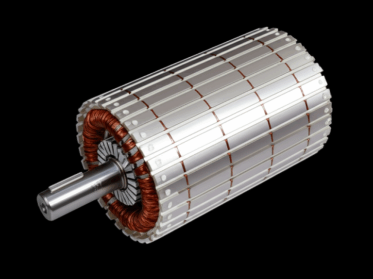
The output terminals of the motor starter are on the overload relay, usually labeled T1, T2, and T3. Connect wires from these terminals and run them to the corresponding terminals in the motor’s connection box. The wires from T1, T2, and T3 connect directly to the windings inside the motor’s stator core lamination.
- T1 -> T1 on Motor
- T2 -> T2 on Motor
- T3 -> T3 on Motor
Pro Tip: For a three-phase motor, you can reverse its direction of rotation by swapping any two of the load-side wires (e.g., swap T1 and T2). Do this only after the initial test proves the motor is running backward.
E. Step 5: Grounding the Motor & Starter Enclosure
A proper ground is a critical safety feature. It provides a safe path for fault current to flow, preventing metal enclosures from becoming energized.
Step-by-Step Wiring Guide: The Control Circuit
The control circuit is the “brains” of the operation. It uses a lower voltage (like 120V or 24V) to control the high-voltage contactor. This circuit determines when the motor starts and stops. We will build a standard “three-wire” control circuit, which is the safest and most common type.
A. Step 1: Identify Your Control Voltage Source
First, determine where your control power is coming from. Some starters have a built-in control power transformer (CPT) that steps down the line voltage to 120V. In other cases, you might be using a separate 120V or 24V power source. For this example, let’s assume we have a 120V control source.
B. Step 2: Wiring the Stop Button (The “Off” Switch)
The Stop button is your first line of control and safety. It’s a Normally Closed (NC) contact.
C. Step 3: Wiring the Start Button (The “On” Switch)
Power flows through the Stop button and then to the Start button.
D. Step 4: Wiring the Holding Contact (The “Memory”)
This is the clever part of the circuit. Since the Start button is momentary, we need a way to keep the circuit “sealed in” or “latched” after you let go of the button. We use a spare Normally Open auxiliary contact on the contactor for this.
When you press Start, the coil energizes, closing this auxiliary contact. Now, even when you release the Start button, power has another path to the coil through the holding contact.
E. Step 5: Wiring the Overload Relay Contacts
This is your motor protection. The Normally Closed (NC) overload contacts must be wired in series so they can break the circuit if the motor is in danger.
Now, if the overload trips, this contact will open, cutting power to the coil and stopping the motor.
F. Step 6: Completing the Coil Circuit
The coil needs a complete circuit to work.
Your control circuit is now complete! When you press Start, you complete a path to the coil. The coil energizes, closing the main contacts (starting the motor) and the holding contact (keeping it running). Pressing Stop or an overload trip will break this path, de-energizing the coil and stopping the motor. This entire process is a practical motor principle in action, translating a simple command into powerful mechanical work.
Final Checks & Testing Before Energizing
You’ve done the hard work, but don’t rush to flip the switch. A few minutes of careful checking can prevent hours of headaches or a dangerous accident.
- Visual Inspection: Go over every connection. Are all screws tight? Are there any stray wire strands that could cause a short circuit? Is the wire insulation intact?
- The “Tug” Test: Gently tug on each wire at its terminal to ensure it’s secure. Loose connections are a major failure point.
- Continuity Checks: With the power still off, use your multimeter’s continuity setting (the one that beeps) to test your control circuit logic.
- Check that you have continuity through your Stop button and no continuity through your Start button.
- Press the Start button and check for continuity from the power source all the way to A1 (you may need to manually press the contactor in to simulate the holding contact).
- Double-Check Diagrams: Compare your physical wiring to the schematic diagram one last time.
- Remove LOTO, Stand Clear, and Energize: Once you are 100% confident, remove your lock and tag. Close the enclosure door. Stand to the side (never directly in front) of the electrical panel and energize the main disconnect.
Initial Start-Up: Press the Start button. The motor should start smoothly. Listen for any unusual noises and observe its rotation. If it’s running backward, perform the LOTO procedure again and swap any two of the T1, T2, T3 wires.
Common Troubleshooting for Motor Starters
Even with careful wiring, things can sometimes go wrong. Here are a few common issues:
- Motor Does Not Start:
- No Control Power: Check for voltage at your control circuit source. Is a fuse blown or a breaker tripped?
- Faulty Coil: Check for continuity across the contactor coil (A1 to A2). If it’s open, the coil is bad.
- Open Overload: Has the overload relay been tripped? Look for a reset button.
- Wiring Error: Go back and carefully trace your control circuit wiring. A single misplaced wire is a common culprit.
- Motor Starts Then Stops Immediately After Releasing Start Button:
- This is a classic symptom of a problem with the holding circuit. Check the wiring to and from the auxiliary contact. Make sure you used a Normally Open contact, not a Normally Closed one.
- Motor Overheats and Trips the Overload:
- Incorrect Overload Setting: Double-check that the amperage dial on the overload relay is set correctly to the motor’s nameplate FLA.
- Mechanical Issue: The motor might be physically binding or trying to move a load that is too heavy.
- Phase Imbalance: In a three-phase system, a lost or low-voltage phase can cause the motor to draw excess current.
- Contactor is Buzzing or Chattering:
- Low Coil Voltage: The voltage supplied to A1/A2 might be too low to fully pull the contacts in.
- Debris: A small piece of dirt or plastic could be preventing the contactor from closing completely.
- Wrong Coil: Ensure the coil voltage rating matches the control circuit voltage you are supplying.
Maintenance Tips for Motor Starters
A well-installed starter needs minimal maintenance, but regular checks can ensure a long service life for all the different types of motor application in your facility.
- Regular Cleaning: Periodically de-energize and lock out the starter to blow out any dust and debris from the enclosure.
- Check for Loose Connections: Heat cycles can cause terminals to loosen over time. As part of annual maintenance, re-torque all power and control connections.
- Verify Overload Settings: If a motor is replaced, always verify that the overload settings match the FLA of the new motor.
Conclusion: Safe & Efficient Motor Control
Wiring a motor starter is a fundamental skill that puts you in control of powerful equipment. By understanding how the individual components—the contactor, overload relay, and push buttons—work together in the power and control circuits, you can create a system that is not only functional but also safe and reliable. The internal components, such as the motor core laminations, are the heart of the machine, and the starter is the brain that protects and controls it.
Always remember that safety is the most important part of any electrical job. The Lockout/Tagout procedure isn’t just a suggestion; it’s a life-saving rule. Take your time, double-check your work, and never hesitate to consult a schematic or ask a qualified professional if you’re unsure about any step. With a methodical approach, you can confidently and competently tackle any motor starter wiring project.