Mastering Stepper Motor Control: A Comprehensive Guide
If you’re an engineer, designer, or hobbyist, you’ve likely faced the challenge of needing precise, repeatable motion in a project. Whether you’re designing a 3D printer, a CNC machine, or a complex robotic arm, the ability to control movement down to a fraction of a degree is critical. This is where the stepper motor shines and if you’ve ever found yourself wondering how to harness its power for your own applications, you’re in the right place.
Stepper motors are the unsung heroes of automation. Unlike standard DC motors that just spin continuously, steppers move in discrete, predictable “steps,” giving you incredible control over position, speed, and direction without complex feedback systems. But how do you go from a motor sitting on your workbench to a fully controlled part of your system?
This guide is designed to be your trusted engineering partner on that journey. We’ll break down the entire process, moving from the fundamental principles to a practical, hands-on example with code. We’ll explain the key components you need, the different ways to control the motor, and how to troubleshoot the common issues that can pop up.
What We’ll Cover
- Understanding Stepper Motors: The Fundamentals
- Essential Components for Stepper Motor Control
- Types of Stepper Motor Control Methods
- Step-by-Step Guide: Controlling a Bipolar Stepper Motor with Arduino & A4988/DRV8825
- Common Challenges & Troubleshooting
- Best Practices for Optimal Stepper Motor Control
- Real-World Applications of Stepper Motors
I. Understanding Stepper Motors: The Fundamentals
Before you can control a stepper motor, you need to understand what makes it tick. Getting a grip on the basics will make wiring, programming, and troubleshooting infinitely easier down the road.
What is a Stepper Motor?
At its core, a stepper motor is an electromechanical device that converts electrical pulses into distinct, mechanical movements. Think of it like a digital motor. Instead of applying a continuous voltage and watching it spin, you send it a series of structured electrical signals, and for each signal, the motor shaft rotates a precise, fixed amount—a “step.”
This step-by-step nature is its superpower. A typical stepper motor, like the popular NEMA 17, might have 200 steps per revolution. This means that if you send it 200 pulses, it will complete exactly one full 360° turn. Send it one pulse, and it moves precisely 1.8°. This predictable behavior is what makes it ideal for applications requiring high precision.
There are two main flavors of stepper motors you’ll encounter:
- Unipolar Stepper Motors: These typically have 5 or 6 wires and are a bit simpler to control from a basic electronics standpoint because their coil windings have a center tap. However, they generally offer less torque for their size.
- Bipolar Stepper Motors: These are the most common type found in applications like 3D printing and CNC machines. They have 4 wires and require a more sophisticated driver circuit to reverse the current flow in their coils. In return for this added complexity, you get significantly better torque and efficiency. This guide will focus primarily on controlling bipolar motors.
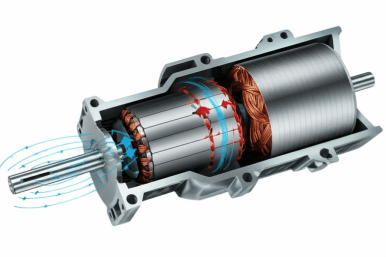
How Stepper Motors Work
The working principle of a stepper motor is all about electromagnetism. Inside the motor, the rotor (the part that spins) has a series of permanent magnets or teeth. The stator (the stationary part) is lined with sets of electromagnets, called coils or phases.
When you send an electrical pulse to one set of coils, you energize it, creating a magnetic field. This magnetic field attracts the teeth of the rotor, causing it to align itself with the energized coil. To make the motor turn, you simply de-energize that coil and energize the next one in the sequence. The rotor then “steps” to the next position to align with the new magnetic field. By continuing this sequence—energize, de-energize, energize the next—you create continuous, step-by-step rotation.
The speed of the motor is determined by how fast you send these pulses and the direction is determined by the sequence in which you energize the coils.
Key Stepper Motor Terminology
As you dive deeper, you’ll run into some specific terms. Here are the most important ones to know:
- Step Angle: The angle the motor shaft rotates for a single step. A 1.8° step angle means 200 steps per revolution (360° / 1.8° = 200).
- Holding Torque: This is the amount of torque required to move the motor shaft from a standstill when the coils are energized. It’s essentially the motor’s ability to hold a position against an external force.
- Detent Torque: The small amount of torque present even when the motor is unpowered, caused by the interaction between the rotor’s permanent magnets and the stator.
- Microstepping: An advanced control technique where you don’t just turn coils fully on or off. Instead, you vary the current to the coils, allowing the rotor to position itself between full steps. This results in incredibly smooth motion and much higher resolution, reducing noise and vibration.
II. Essential Components for Stepper Motor Control
You can’t control a stepper motor with just a prayer and a battery. You need a small ecosystem of components working together. Here’s a look at the essential hardware.
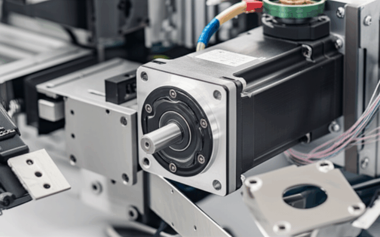
The Stepper Motor Itself
First, you need the motor. When selecting one, you’ll look at a few key specifications:
- NEMA Size: This refers to the faceplate dimensions of the motor (the NEMA standard). NEMA 17 is extremely common for hobbyist projects like 3D printers while NEMA 23 and larger are used for more powerful CNC machines.
- Voltage & Current Rating: Every motor has a rated voltage and, more importantly, a current rating per phase (e.g., 1.5A/phase). The current rating is crucial for setting up your driver correctly.
- Torque Rating: Usually measured in ounce-inches (oz-in) or Newton-centimeters (N-cm), this tells you the motor’s power.
Stepper Motor Driver (The Brain’s Muscle)
A stepper motor can’t be connected directly to a microcontroller like an Arduino. The microcontroller’s pins can’t supply the high current the motor’s coils need. This is where the motor driver comes in.
The driver acts as an intermediary, taking low-power control signals (like STEP and DIRECTION) from your microcontroller and translating them into the high-current, sequenced pulses required to energize the motor coils. It’s the muscle that does the heavy lifting for the brain.
Popular drivers include:
- A4988: A cost-effective, reliable workhorse. It’s a great starting point for many projects and supports up to 1/16th microstepping.
- DRV8825: A step up from the A4988, offering higher current capacity and finer 1/32nd microstepping for smoother motion.
- TMC2208/TMC2209 (Trinamic drivers): These are the modern “silent” drivers. They feature advanced technologies like StealthChop™ that make motor operation incredibly quiet and smooth. Their adoption has surged in recent years, especially in 3D printers, where noise reduction is a huge user benefit.
Microcontroller or Control Board
This is the brain of the operation. It’s where your code lives and it generates the signals that tell the driver what to do.
- Arduino (Uno, Nano): The go-to for beginners. It’s affordable, easy to program, and supported by a massive community and extensive libraries.
- ESP32: A more powerful option that includes built-in Wi-Fi and Bluetooth, making it perfect for IoT or wirelessly controlled projects.
- Raspberry Pi: A full-fledged single-board computer. You’d choose a Pi for more complex applications that require an operating system, networking, and significant processing power, such as running advanced motion control software like Klipper or OctoPrint.
Power Supply
Your motor and driver need a separate, robust power supply. You can’t power them from your microcontroller’s 5V output. The power supply must meet two criteria:
- Voltage: It should be within the operating range of your motor driver (e.g., 8V-35V for an A4988) and is often higher than the motor’s rated voltage to achieve better high-speed performance. A 12V or 24V supply is very common.
- Current: It must be able to supply enough current for all the motors you plan to run simultaneously.
Wiring & Connectivity
Don’t overlook the basics. You’ll need a breadboard for prototyping, a good set of jumper wires, and appropriately gauged wires for connecting the power supply and motor to the driver.
III. Types of Stepper Motor Control Methods
There are several ways to drive a stepper motor, ranging from simple to highly advanced. The method you choose depends on your need for speed, torque, and smoothness.
A. Basic Step Control
These methods involve turning the motor coils fully on or off in a sequence.
- Full-Step Control: This is the simplest method. In one common mode, two coils are energized at a time. The motor moves one full step for each pulse, providing the maximum rated torque. However, it’s also the roughest and loudest mode of operation.
- Half-Step Control: This method doubles the motor’s resolution by alternating between energizing two coils and then just one coil. This creates steps that are half the size of a full step (e.g., 0.9° instead of 1.8°), resulting in smoother motion. The trade-off is slightly less torque at certain positions.
B. Advanced Control Methods
Modern control relies on more sophisticated techniques handled by the driver IC.
- Microstepping: This is the gold standard for smooth motion. Instead of full-on/full-off signals, the driver uses Pulse Width Modulation (PWM) to deliver partial currents to the coils. This allows the rotor to stop at positions between full steps. A driver set to 1/16 microstepping, for example, divides each 1.8° full step into 16 smaller microsteps, achieving a resolution of 0.1125° per pulse. According to engineering specifications, some advanced drivers can achieve up to 1/256 microstepping, resulting in near-silent, fluid movement.
- Open-Loop Control: This is the standard operating mode for most stepper systems. You send a command to move a certain number of steps, and you assume the motor did it. There’s no feedback to confirm the final position. It’s simple and cost-effective, and highly reliable as long as the motor is not overloaded.
- Closed-Loop Control: For critical applications where losing a step would be catastrophic, you can add an encoder to the motor shaft. This encoder provides positional feedback to the controller, creating a closed-loop system. If the controller detects that the motor has missed a step (due to a crash or overload), it can take corrective action. This combines the precision of a stepper with the reliability of a servo motor.
IV. Step-by-Step Guide: Controlling a Bipolar Stepper Motor with Arduino & A4988/DRV8825
Let’s get practical. Here’s how you can get a NEMA 17 bipolar stepper motor spinning using an Arduino and a common A4988 or DRV8825 driver.
A. Prerequisites
Hardware:
- Arduino Uno or Nano
- Bipolar Stepper Motor (NEMA 17 is a great choice)
- A4988 or DRV8825 Stepper Motor Driver
- Breadboard and Jumper Wires
- External Power Supply (e.g., 12V, 2A)
- A small capacitor (around 100µF) to stabilize the power supply to the driver.
Software:
- Arduino IDE installed on your computer.
B. Wiring Diagram
Wiring is the most critical step. An incorrect connection can damage your driver or microcontroller. Follow this diagram carefully.
![A simple wiring diagram showing connections between Arduino, A4988 driver, NEMA 17 motor, and a 12V power supply.]
Key Connections:
.
C. Programming the Arduino
We’ll write a simple sketch that rotates the motor one revolution clockwise, pauses, and then one revolution counter-clockwise.
This code directly manipulates the STEP and DIR pins, which is a fundamental way to understand how drivers work.
// Define the pin connectionsconst int stepPin = 2; const int dirPin = 3; const int enablePin = 4;// Define motor propertiesconst int stepsPerRevolution = 200; // For a 1.8 degree motorvoid setup() { // Set the pins as outputs pinMode(stepPin, OUTPUT); pinMode(dirPin, OUTPUT); pinMode(enablePin, OUTPUT); // Enable the driver by pulling the EN pin LOW digitalWrite(enablePin, LOW);}void loop() { // --- Rotate Clockwise --- // Set the direction to clockwise digitalWrite(dirPin, HIGH); // Pulse the step pin 200 times for one full revolution for(int x = 0; x < stepsPerRevolution; x++) { digitalWrite(stepPin, HIGH); delayMicroseconds(500); // This delay controls the speed digitalWrite(stepPin, LOW); delayMicroseconds(500); } delay(1000); // Pause for one second // --- Rotate Counter-Clockwise --- // Set the direction to counter-clockwise digitalWrite(dirPin, LOW); // Pulse the step pin 200 times for one full revolution for(int x = 0; x < stepsPerRevolution; x++) { digitalWrite(stepPin, HIGH); delayMicroseconds(500); digitalWrite(stepPin, LOW); delayMicroseconds(500); } delay(1000); // Pause for one second}Explanation:
- The code first defines which Arduino pins are connected to the driver’s STEP, DIR, and ENABLE pins.
- In
setup(), we set these pins as outputs and pull the ENABLE pin LOW to activate the driver. - In the
loop(), we first set the direction (HIGH for clockwise). - The
forloop then creates 200 pulses by rapidly setting thestepPinHIGH and then LOW. Each pulse tells the driver to move the motor one step. - The
delayMicroseconds()calls control the time between pulses, which dictates the motor’s speed. A smaller delay means a faster motor.
D. Testing and Calibration
- Look up the formula for your specific driver (it involves measuring the voltage on the potentiometer).
- Start with a low setting and gradually increase it until the motor runs smoothly without skipping steps and without getting excessively hot.
V. Common Challenges & Troubleshooting
Even with a perfect setup, you can run into issues. Here’s a quick guide to fixing common problems.
- Motor not moving or just vibrating: This is the most common issue.
- Check Wiring: Double and triple-check all your connections, especially the motor coil pairs.
- Insufficient Power: Your power supply might not be providing enough current, or the current limit on your driver is set too low.
- Enable Pin: Ensure the ENABLE pin is being pulled LOW correctly in your code.
- Overheating driver or motor:
- Current Too High: The current limit on your driver is set too high. Turn it down.
- Inadequate Cooling: The driver chip needs a heatsink (they usually come with one). For a motor under heavy load, it may also require fan cooling.
- Lost steps (motor doesn’t move as far as it should):
- Overload: The torque required to move the load is greater than what the motor can provide.
- Acceleration Too High: You’re trying to start or stop the motor too abruptly. Implement acceleration/deceleration ramps in your code.
- Incorrect Voltage: While you can run motors at higher voltages for better performance, too low a voltage can limit torque at high speeds.
- Noise and resonance: Stepper motors can be noisy, especially at certain speeds.
- Use Microstepping: This is the number one solution for reducing noise and vibration.
- Mechanical Damping: Use flexible motor mounts to absorb vibrations.
- Incorrect rotation direction:
- Software: Flip the logic on your DIR pin (change
digitalWrite(dirPin, HIGH)toLOWand vice versa). - Hardware: Reverse the connections of one—and only one—of the motor coil pairs (e.g., swap 1A and 1B).
VI. Best Practices for Optimal Stepper Motor Control
To move from a functional setup to a reliable and professional one, follow these best practices.
- Proper Driver Selection and Current Limiting: This is non-negotiable. Always choose a driver that can handle your motor’s current and set the limit correctly to ensure the longevity of your components.
- Sizing the Power Supply Correctly: Don’t skimp on your power supply. Ensure it has a slightly higher current rating than the total your system will draw to prevent voltage drops under load.
- Heat Management: Heat is the enemy of electronics. Always use the included heatsinks on your drivers. For demanding applications, consider active cooling with a fan. The internal construction of the motor, including its electrical steel laminations, plays a role in its thermal properties.
- Cable Length and Shielding: For long cable runs, use shielded, twisted-pair cables to protect the control signals from electrical noise, which can cause missed steps.
- Implementing Acceleration/Deceleration Ramps: Instead of starting and stopping at full speed, smoothly ramp the speed up and down. This prevents the motor from stalling and losing steps, especially with heavy loads. Libraries like
AccelStepper.hfor Arduino make this easy. - Using Closed-Loop Feedback (When Necessary): For mission-critical applications where positional accuracy is paramount, investing in a closed-loop system with an encoder provides a safety net against lost steps.
VII. Real-World Applications of Stepper Motors
The precision of stepper motors has made them indispensable in countless fields. According to industry analyses, 3D printing and CNC machines account for a significant portion of NEMA-sized stepper motor consumption.
- 3D Printers & CNC Machines: Steppers control the precise movement of the print head and build plate (in 3D printers) or the cutting tool and workpiece (in CNC mills). The quality of the motor core laminations is a key factor in the performance and efficiency of these motors.
- Robotics: They are used for articulated joints, grippers, and wheeled platforms where precise, repeatable movements are essential.
- Camera Pan/Tilt Systems: Steppers allow for smooth, controlled, and repeatable camera movements for security, photography, and videography.
- Medical and Lab Equipment: Automated fluid pumps, sample handlers, and scanners all rely on the precision of stepper motors.
- Valves and Actuators: In industrial automation, steppers provide precise control over flow rates and linear positioning.
Conclusion
Stepper motors are a powerful and accessible technology for achieving precise motion control. By understanding the fundamentals of how they work, selecting the right components, and implementing proper control techniques, you can unlock a world of possibilities for your projects.
We’ve journeyed from the basic principles of electromagnetism to a hands-on wiring and coding example. You’ve learned how to choose a motor and driver, how to troubleshoot common problems, and how to apply best practices for a robust setup. The key takeaway is that control is systematic: a good power supply, a capable driver, and clean signals from a microcontroller are the pillars of success.
Now, it’s your turn to experiment. Start with the simple code provided, then explore more advanced libraries like AccelStepper, try different microstepping settings, and see how they impact the performance of your motor. With these tools and knowledge, you are well-equipped to master stepper motor control and bring your automated creations to life.