What is a Stator? The Essential Guide to Its Function & Importance
Every design engineer and procurement manager faces the critical challenge of maximizing motor efficiency while managing performance, reliability, and cost. If you’ve ever found yourself deep in a datasheet, weighing the trade-offs between different motor components and their impact on your final product, you’re in the right place. At the very heart of this complex equation lies a component that is fundamental yet often overlooked: the stator. It’s the silent, stationary partner in the dance of electromagnetism, and understanding it is key to unlocking superior performance.
The term “stator motor” is a common shorthand, but it really refers to the stator of a motor—the foundational element that makes rotation possible. From the industrial pumps driving our infrastructure to the precision motors in electric vehicles and robotic arms, the stator’s design dictates everything from power consumption to operational lifespan. This guide will demystify this essential component, moving beyond a simple definition to explore its anatomy, function, and critical role in modern technology.
What We’ll Cover
- What Exactly is a Stator? A clear, foundational definition.
- Anatomy of a Stator: A breakdown of its key components.
- How a Stator Works: The physics behind creating motion from stillness.
- Stator vs. Rotor: Understanding the dynamic partnership.
- Types of Stators: Exploring variations for different motor technologies.
- Common Applications: Where stators are making an impact today.
- Why Stator Design and Materials Matter: The link between stator quality and performance.
- Your Engineering Takeaway: Key points to guide your design and purchasing decisions.
What Exactly is a Stator? A Clear Definition
In the world of electromechanical systems, the stator is the stationary part of a rotary system. Think of it as the powerhouse or the arena within which the action happens. Its counterpart, the rotor, is the rotating component that does the physical work. While the rotor gets the glory of spinning, it’s the stator that creates the invisible but powerful magnetic field that directs the entire show.
The fundamental function of a stator is to serve as the stationary housing for the field windings or permanent magnets. When electrical energy is supplied, these windings generate a precisely controlled magnetic field. It’s this magnetic field that interacts with the rotor, inducing it to turn and converting electrical energy into the mechanical energy that drives everything from a fan blade to the wheels of a car.
In a generator or alternator, this process is reversed. Mechanical energy (like wind turning a turbine) spins the rotor within the stator’s magnetic field, inducing an electrical current in the stator’s windings. In this role, the stator becomes the component that generates electricity. So, whether it’s a motor or a generator, the stator is the critical, non-moving element responsible for orchestrating the energy conversion.
Anatomy of a Stator: Breaking Down the Key Components
A stator isn’t a single, solid piece of metal. It’s a carefully engineered assembly of three primary components, each with a specific job to do. Understanding these parts reveals why stator design is such a critical aspect of motor performance.
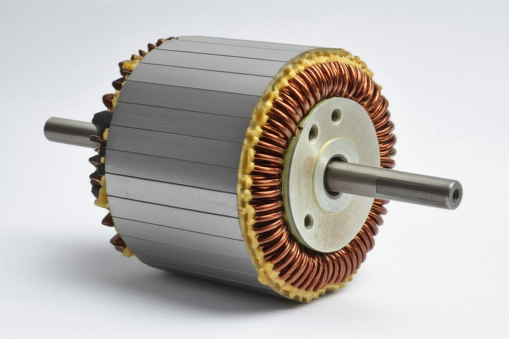
1. The Stator Core
The foundation of the stator is the stator core. Its primary job is to provide a highly efficient path for the magnetic flux, essentially concentrating and directing the magnetic field exactly where it needs to go. If the windings are the “voice,” the core is the “megaphone” that focuses the sound.
This core is not a solid block of steel. Instead, it’s constructed from a stack of very thin, insulated sheets of electrical steel, typically a silicon-steel alloy. These individual sheets are called laminations. The reason for this construction is to combat a major source of energy loss: eddy currents.
Think of eddy currents as small, unwanted whirlpools of electrical current that form within a solid metal core when it’s exposed to a changing magnetic field. These whirlpools do no useful work; they only generate heat, which is wasted energy. By using thin, insulated silicon steel laminations, engineers create barriers that effectively break up these large whirlpools into thousands of tiny, insignificant ones. This dramatically reduces energy loss, lowers operating temperatures, and improves overall motor efficiency. The thickness and material grade of these laminations are critical design choices that directly impact performance, especially in high-frequency applications.
2. Stator Windings (Coils)
Set into slots within the stator core are the stator windings. These are coils of highly conductive, insulated copper wire. When an electric current passes through these coils, they become electromagnets, generating the magnetic field that drives the motor. The arrangement, thickness, and number of turns in these copper windings are precisely calculated to produce a magnetic field of the desired strength and shape.
There are two primary configurations for these windings:
- Distributed Winding: The coils are spread out across multiple slots in the stator core. This approach typically produces a smoother rotating magnetic field and a more sinusoidal back EMF (Electromotive Force), which is desirable for low-noise and low-vibration applications.
- Concentrated Winding: Each coil is wound around a single stator “tooth.” This design can be more compact, reduce the total length of copper wire needed (which can lower costs and resistive losses), and is common in high-power-density motors like Brushless DC (BLDC) motors.
The quality of the insulation around the copper wire is also paramount. Stator insulation breakdown is one of the most common causes of motor failure, often triggered by overheating, voltage spikes, or vibration.
3. The Stator Frame (Housing)
The final component is the stator frame, also known as the housing or yoke. This is the outer shell that holds everything together. Its functions are threefold:
How a Stator Works: The Engine’s Heartbeat
The magic of a motor lies in turning stationary electrical inputs into continuous rotational motion. This transformation is orchestrated by the stator through the principle of electromagnetism and, in most modern motors, the creation of a rotating magnetic field.
Creating the Magnetic Field
At its most basic level, when you pass an electric current through a wire, it generates a magnetic field around that wire. By coiling that wire (creating a winding) around a ferromagnetic core (the stator core), you create a powerful and controllable electromagnet. The direction of the magnetic field (its north and south poles) depends on the direction of the current flow.
The Magic of the Rotating Magnetic Field (RMF)
This is where things get really clever, especially in AC motors. Instead of just one winding, an AC stator has multiple sets of windings, or “phases.” In a common three-phase stator, there are three separate windings physically offset from each other by 120 degrees around the core.
When connected to a three-phase AC power supply, each winding receives a current that is also out of sync by 120 degrees. The result is a beautifully choreographed sequence:
The incredible outcome is a magnetic field that smoothly rotates around the stator’s inner circumference—all without a single moving part. The speed of this rotation, known as the synchronous speed, is determined by the frequency of the AC power supply and the number of magnetic poles designed into the stator windings.
The Stator-Rotor Interaction
Once the stator has established this rotating magnetic field, the rotor is compelled to follow it. This happens in a couple of different ways depending on the motor type:
- Induction Motors: In an AC induction motor, the stator’s rotating magnetic field sweeps across the rotor’s conductive bars. According to Faraday’s Law of Induction, this induces a powerful electrical current within the rotor. This induced current creates its own magnetic field in the rotor, which opposes the stator’s field (Lenz’s Law). The interaction between these two fields generates the torque that forces the rotor to spin, effectively “chasing” the stator’s field but never quite catching up to it.
- Synchronous & BLDC Motors: In these motors, the rotor contains its own magnets (either permanent magnets or electromagnets). The stator’s rotating magnetic field directly grabs onto the rotor’s magnetic poles—like the attraction between two bar magnets—and pulls them along in perfect sync. This provides highly precise speed control and excellent efficiency, as there are no energy losses from inducing current in the rotor.
Stator vs. Rotor: A Tale of Two Components
It’s impossible to fully understand the stator without comparing it to its dynamic partner, the rotor. Their relationship is one of perfect synergy; one is useless without the other.
| Feature | Stator | Rotor |
|---|---|---|
| Movement | Stationary (Fixed to the motor housing) | Rotating (Spins on a shaft to deliver mechanical power) |
| Primary Role | Creates the primary magnetic field. | Interacts with the stator’s field to produce torque. |
| Components | Stator core, windings, and frame. | Rotor core, windings or magnets, and a central shaft. |
| Connection | Directly connected to the external electrical power source. | Typically not directly connected to a power source (except in some DC and wound-rotor types). |
| Analogy | The “racetrack” that defines the path. | The “car” that moves along the track. |
The physical space between the stator and the rotor is called the air gap. The size of this gap is a critical design parameter. A smaller air gap leads to a stronger magnetic coupling and higher efficiency, but it requires much tighter manufacturing tolerances and can be more susceptible to issues from vibration or bearing wear.
Types of Stators: Not All Are Created Equal
While the basic principle remains the same, stator design varies significantly based on the type of motor and its intended application.
AC Motor Stators
- Induction Motor Stator: This is the most common type used in industry. The stator is designed to create a powerful rotating magnetic field that induces current in a simple, rugged “squirrel cage” rotor. They are known for their reliability and cost-effectiveness.
- Synchronous Motor Stator: The stator’s function is similar to an induction motor’s, but it’s paired with a rotor that has its own magnetic field (from permanent magnets or DC-energized windings). This forces the rotor to lock in and rotate at the same synchronous speed as the stator’s field, making them ideal for applications requiring precise speed control or power factor correction.
DC Motor Stators
- Brushed DC Motor Stator: In traditional brushed DC motors, the stator (often called the “field”) creates a stationary magnetic field. This can be done with permanent magnets or with “field windings” that act as electromagnets. The commutation (the switching of current) happens mechanically in the rotor via brushes.
- Brushless DC (BLDC) Motor Stator: BLDC motors essentially flip the design. The rotor contains the permanent magnets, and the stator houses the windings. There are no brushes; instead, electronic sensors and a controller switch the current in the stator windings in a precise sequence to create a rotating magnetic field that “pulls” the rotor along. This design leads to higher efficiency, less maintenance, and a much better power-to-weight ratio. The design of BLDC stator cores is critical for achieving the high power density seen in EVs and drones.
Where You’ll Find Stators: Common Applications
Stators are the unsung heroes inside countless devices that power our world. Their applications span nearly every industry:
- Industrial Machinery: They are the heart of industrial motors that run pumps, fans, compressors, conveyors, and machine tools in factories worldwide.
- Automotive Industry: The transition to electric vehicles (EVs) is driven by highly efficient BLDC and synchronous motors, where stator design directly impacts range and performance. Even conventional cars rely on an alternator stator to charge the battery.
- Consumer Appliances: From the motor in your washing machine and refrigerator compressor to the one in your vacuum cleaner and power tools, stators are everywhere in the home.
- Energy Generation: Massive generator stators are essential components in power plants. A stator in a wind turbine generator, for example, is responsible for converting the mechanical rotation of the blades into grid-scale electricity.
- Aerospace & Robotics: In these fields, power density and precision are paramount. Specialized stators are used in actuators for flight control systems, high-torque servo motors for robotic joints, and motors for drones.
- Medical Devices: Miniature stators power high-speed surgical drills, diagnostic imaging equipment, and other critical medical tools where reliability is non-negotiable.
Why Stator Design and Materials Matter
For engineers and designers, the stator isn’t just a component—it’s a collection of variables that can be optimized to achieve specific performance goals. The choice of materials and construction of the stator core lamination has a profound impact on the motor’s final characteristics.
1. Motor Efficiency and Core Losses:
The quality of the silicon steel used in the core directly affects efficiency. High-grade steels with low hysteresis losses (energy lost as magnetic domains flip back and forth) and thin laminations to minimize eddy currents are crucial. An optimized stator design is a primary reason why modern IE4 “Super Premium Efficiency” motors can achieve efficiencies of 96% or higher, offering significant energy savings. For instance, replacing an older IE1 motor with an IE4 unit in a continuous-duty application like a pump can cut that motor’s electricity consumption by 15-20%.
2. Power Density and Thermal Management:
The goal is often to get more power out of a smaller, lighter package. This is especially true in EV and aerospace applications. Advanced stator designs, such as those using hairpin-style rectangular copper windings, can significantly increase the slot fill factor—the amount of copper packed into the stator slots. A higher fill factor (up to 70-80% for hairpins vs. ~40% for traditional round wire) reduces resistive losses and allows for higher current, boosting power output. However, this increased power density also generates more heat, making stator cooling methods like liquid cooling jackets absolutely critical.
3. Reliability and Lifespan:
A motor’s life is often dictated by the health of its stator. Stator overheating is the enemy, as it degrades the winding insulation over time, eventually leading to a short circuit and motor failure. In fact, stator winding insulation breakdown accounts for an estimated 30-40% of all industrial motor failures. Proper design, high-quality insulation materials (rated by insulation class), and robust manufacturing processes like varnishing are essential for ensuring a long, reliable service life.
Your Engineering Takeaway: The Unsung Hero
The stator may be the stationary component, but it is far from passive. It is the active, foundational element that creates the electromagnetic environment for motion or power generation. As you design or specify your next motor, remember these key points:
- The Stator Sets the Stage: It generates the critical magnetic field that drives the entire system. Its design is the starting point for a motor’s performance characteristics.
- Losses Are Your Enemy: Energy losses in the stator, primarily from eddy currents in the core and resistive heating in the windings, directly translate to lower efficiency and excess heat. High-quality motor core laminations are your first line of defense.
- Materials Matter Immensely: The grade of silicon steel, the purity of the copper, and the class of the insulation are not minor details—they are fundamental choices that dictate the motor’s efficiency, power density, and durability.
- Design is a Trade-Off: Optimizing a stator involves balancing competing factors like cost, weight, size, efficiency, and manufacturability. The ideal design for an industrial fan motor is vastly different from that of an EV traction motor.
By understanding the principles behind the stator, you empower yourself to ask the right questions, specify the right components, and ultimately build better, more efficient, and more reliable products. It’s the unsung hero, quietly enabling the technology that moves our world forward.